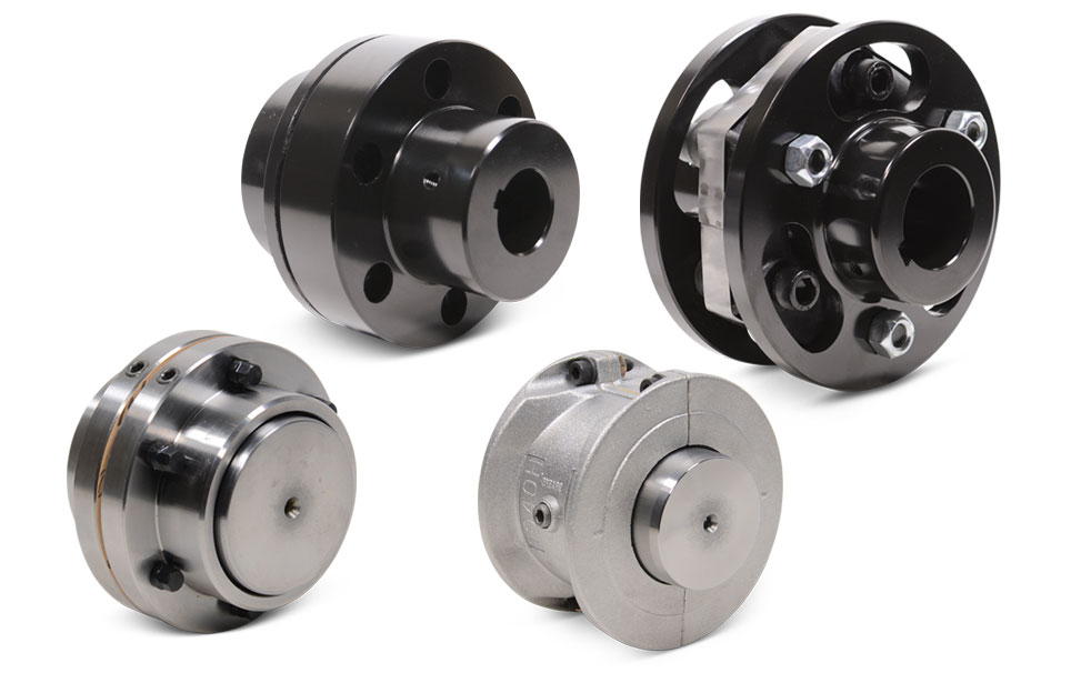
Product Description
Product Description
1. The allowable compensation quantity listed in the table refers to the relative offset of 2 axes formed by the comprehensive factors such as vibration, shock, deformation and temperature change caused by manufacturing error, installation error and working load change under working condition.
2. The maximum allowable angular deviation of the coupling shall not exceed ±5°.
The maximum opening value is a circular hole or a tapered hole with a keyway.
Main applications:
DWZ disc eddy current brake is mainly used as load in loading dynamometer equipment. it is experimental apparatus which can measure the dynamic mechanical properties, especially in dynamic loading test whose power value is small or tiny, also can be treated as suction power devices of other dynamic devices.
DW series disc eddy current dynamometer is, is that add device for measuring torque and rotational speed on DWZ series disc eddy current brake, it is experimental apparatus which can measure the dynamic mechnical properties, especial in dynamic loading test whose power value is small or tiny.
CW eddy current brake as a load is mainly used to measure the mechanical characteristics of inspection equipment, it and other control instrument (including loading apparatus, torque speed sensor and torque power acquisition instrument etc.) can be composed of eddy current dynamometer can be used for performance testing of the internal combustion engine, motor, gas turbine, automobile and its dynamic mechanical components, compared with other power measuring device, the CW series power measuring device has the advantages of reliability, high stability and practicability.
| Eddy current brake/dynamometer | Rated Power | Rated torque | Rated speed | Maximum rotational speed | Turning inertia | Maximum excitation voltage | Maximum excitation Current | Cooling water pressure | Flow of the cooling water |
| DWZ/DW-0.75 | 0.75 | 5 | 2000-2600 | 16000 | 0.002 | 80 | 3 | 0.1~0.3 | 1 |
| DWZ/DW-3 | 3 | 10 | 2000-2600 | 14000 | 0.003 | 80 | 3 | 0.1~0.3 | 2 |
| DWZ/DW-6 | 6 | 25 | 2000-2600 | 14000 | 0.003 | 80 | 3 | 0.1~0.3 | 3 |
| DWZ/DW-10 | 10 | 50 | 2000-2600 | 13000 | 0.01 | 80 | 3 | 0.1~0.3 | 4.5 |
| DWZ/DW-16 | 16 | 70 | 2000-2600 | 13000 | 0.02 | 80 | 3.5 | 0.1~0.3 | 6.5 |
| DWZ/DW-25 | 25 | 120 | 2000-2600 | 11000 | 0.05 | 80 | 3.5 | 0.1~0.3 | 15 |
| DWZ/DW-40 | 40 | 160 | 2000-2600 | 10000 | 0.1 | 90 | 4 | 0.1~0.3 | 25 |
| DWZ/DW-63 | 63 | 250 | 2000-2600 | 9000 | 0.18 | 90 | 4 | 0.1~0.3 | 45 |
| DWZ/DW-100 | 100 | 400 | 2000-2600 | 8500 | 0.32 | 120 | 4 | 0.1~0.3 | 60 |
| DWZ/DW-160 | 160 | 600 | 2000-2600 | 8000 | 0.52 | 120 | 5 | 0.1~0.3 | 100 |
| DWZ/DW-250 | 250 | 1100 | 2000-2600 | 7000 | 1.8 | 150 | 5 | 0.2~0.4 | 180 |
| DWZ/DW-300 | 300 | 1600 | 2000-2600 | 6000 | 2.7 | 150 | 5 | 0.2~0.4 | 210 |
| DWZ/DW-400 | 400 | 2200 | 2000-2600 | 5000 | 3.6 | 180 | 10 | 0.2~0.4 | 300 |
| DWZ/DW-630 | 630 | 3600 | 2000-2600 | 5000 | 5.3 | 180 | 10 | 0.2~0.4 | 450 |
/* January 22, 2571 19:08:37 */!function(){function s(e,r){var a,o={};try{e&&e.split(“,”).forEach(function(e,t){e&&(a=e.match(/(.*?):(.*)$/))&&1
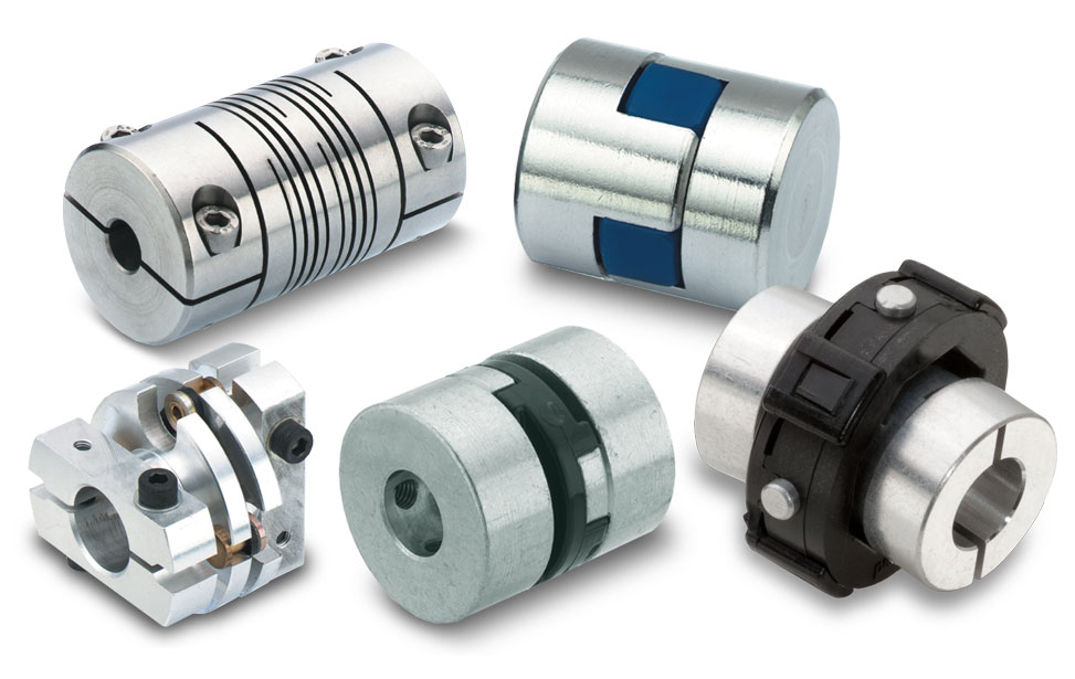
Best Practices for Installing a Motor Coupling for Optimal Performance
Proper installation of a motor coupling is essential to ensure optimal performance and reliability of the power transmission system. Follow these best practices when installing a motor coupling:
1. Correctly Match Coupling Type:
Select a motor coupling type that is suitable for the specific application and operating conditions. Consider factors like torque requirements, misalignment tolerance, and environmental factors when choosing the coupling.
2. Ensure Proper Alignment:
Achieve precise alignment between the motor and driven equipment shafts before installing the coupling. Misalignment can lead to premature wear and reduced efficiency.
3. Check Shaft Endplay:
Verify that the shafts have the correct endplay to allow for thermal expansion and contraction. Inadequate endplay can lead to binding or increased stress on the coupling and connected components.
4. Clean Shaft Surfaces:
Ensure that the shaft surfaces are clean and free of any debris or contaminants before installing the coupling. Clean surfaces promote proper coupling engagement and reduce the risk of slippage.
5. Use Correct Coupling Fasteners:
Use the specified fasteners, such as bolts or set screws, provided by the coupling manufacturer. Tighten the fasteners to the recommended torque values to secure the coupling properly.
6. Verify Keyway Alignment:
If the coupling has a keyway, ensure that it aligns correctly with the key on the motor and driven equipment shafts. Proper keyway alignment prevents rotational slippage and ensures efficient torque transmission.
7. Lubrication:
If the coupling requires lubrication, apply the appropriate lubricant as recommended by the manufacturer. Proper lubrication reduces friction and wear on coupling components.
8. Perform Trial Run:
Before putting the system into full operation, perform a trial run to check for any abnormalities or vibrations. Monitor coupling performance and check for leaks, noises, or other signs of issues.
9. Regular Inspection and Maintenance:
Conduct regular inspections and maintenance on the motor coupling and the entire power transmission system. Check for wear, alignment, and any signs of damage, and address any issues promptly.
10. Follow Manufacturer Guidelines:
Always follow the manufacturer’s installation guidelines and recommendations for the specific coupling model. Manufacturer guidelines provide essential information for optimal performance and safe operation.
By adhering to these best practices, you can ensure that the motor coupling functions efficiently and contributes to the overall performance and reliability of the mechanical system.
“`
Can Motor Couplings Handle Reversing Loads and Shock Loads Effectively?
Yes, motor couplings are designed to handle both reversing loads and shock loads effectively, making them suitable for a wide range of industrial applications. Here’s how motor couplings can handle these types of loads:
Reversing Loads:
Motor couplings are capable of transmitting torque in both forward and reverse directions. When the driven equipment experiences changes in direction, the motor coupling efficiently transfers torque from the motor to the driven equipment without any loss in performance. This capability is crucial in applications that require frequent changes in rotational direction, such as reversing drives in industrial machinery.
Shock Loads:
Motor couplings, especially those with elastomeric elements, have excellent shock-absorbing properties. When subjected to sudden shocks or impacts, such as during machine start-ups or sudden stops, the elastomeric material in the coupling helps dampen and absorb the impact energy. This protects the motor, driven equipment, and other components in the power transmission system from damage or excessive stress.
The ability of motor couplings to handle reversing loads and shock loads effectively is a result of their flexible and durable construction. Flexible couplings, in particular, can accommodate misalignments and absorb vibrations, further contributing to their ability to handle dynamic loads. However, it’s essential to consider the specific application’s requirements and select the appropriate coupling type and size that matches the expected reversing and shock load characteristics.
Proper installation, alignment, and regular maintenance of motor couplings are also critical factors in ensuring their optimal performance under reversing and shock load conditions. Regular inspection and monitoring can help identify any signs of wear or damage and allow for timely maintenance, contributing to the long-term reliability and efficiency of the power transmission system.
“`
How to Diagnose and Fix Common Issues with Motor Couplings
Diagnosing and fixing common issues with motor couplings is essential to ensure optimal performance and prevent equipment failures. Here are steps to diagnose and address common coupling problems:
1. Visual Inspection:
Perform a visual inspection of the motor coupling regularly. Look for signs of wear, cracks, or any visible damage. Check for proper alignment and coupling installation.
2. Vibration Analysis:
Use vibration analysis to identify abnormal vibrations in the coupling or connected machinery. Excessive vibration can indicate misalignment, damaged coupling elements, or worn components.
3. Check for Misalignment:
Verify the alignment between the motor and driven equipment shafts. Misalignment can lead to coupling failure and increased stress on the machinery. Adjust the alignment if necessary.
4. Listen for Unusual Noises:
Listen for any unusual noises during motor operation, such as rattling or grinding sounds. Unusual noises may indicate a loose coupling or damaged components.
5. Inspect Coupling Fasteners:
Check the tightness of coupling fasteners, such as bolts or set screws. Loose fasteners can lead to misalignment and coupling slippage.
6. Lubrication:
If the coupling requires lubrication, ensure it is adequately lubricated. Lack of lubrication can cause increased friction and wear, leading to premature failure.
7. Replace Damaged Components:
If you find any signs of damage or wear during inspection, replace the damaged coupling elements promptly. This may include replacing elastomeric inserts, worn gear teeth, or other damaged parts.
8. Verify Torque Limiting (if applicable):
If the coupling has torque-limiting features, check that they are functioning correctly. These features protect the motor and equipment from overload situations.
9. Monitor Coupling Performance:
Regularly monitor the coupling’s performance to detect any changes or issues early on. Continuous monitoring can prevent more severe problems and reduce downtime.
10. Seek Professional Help:
If you are unsure about diagnosing or fixing a coupling issue, consider seeking assistance from a qualified technician or engineer.
By conducting regular inspections and addressing any problems promptly, you can extend the lifespan of the motor coupling and maintain the efficiency and reliability of the entire power transmission system.
“`

editor by CX 2024-05-02
by
Leave a Reply