Product Description
Product Description
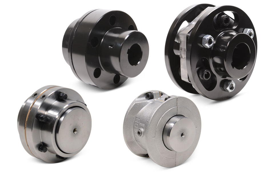
Hot Selling GL Type Spline Rigid Shaft Couplings Roller Chain Coupling For Industry Machine
FEATURES
Manufactured according to relevant industrial standards
Available in many sizes, ratings, and product types, including flexible shaft couplings and OK couplings
Fabricated from a variety of high-grade steel
BENEFITS
Several surface treatment processes protect against corrosion
Customized products are available
Large couplings withstand very high torque
Flexible shaft couplings compensate for shaft misalignment
The chain coupling consists of two-strand roller chains, 2 sprockets and AL-Alloy cover, features simple and compact structure, and high flexibility, power transmission capability and durability.
What’s more ,the chain coupling allows simple connection/disconnection, and the use of the housing enhances safety and durability.
The number of roller depends CHINAMFG the specific application
| Chain No. | Pitch
P mm |
Roller diameter d1max mm |
Width between inner plates b1min mm |
Pin diameter d2max mm |
Pin length | Inner plate depth h2max mm |
Plate thickness
Tmax mm |
Tensile strength
Qmin kN/lbf |
Average tensile strength
Q0 |
Weight per meter q kg/m |
|
| Lmax
mm |
Lcmax
mm |
||||||||||
| 08AF36 | 12.700 | 7.95 | 21.70 | 3.96 | 30.8 | 32.1 | 12.00 | 1.50 | 13.8/3135.36 | 16.20 | 1.070 |
| 10AF13 | 15.875 | 10.16 | 16.31 | 5.08 | 27.6 | 29.1 | 15.09 | 2.03 | 22.2/5045 | 27.50 | 1.350 |
| 10AF71 | 15.875 | 10.16 | 19.00 | 5.08 | 30.5 | 32.2 | 15.09 | 2.03 | 21.8/4901 | 24.40 | 1.480 |
| *10AF75 | 15.875 | 10.16 | 45.60 | 5.08 | 57.0 | 58.5 | 15.09 | 2.03 | 21.8/4901 | 24.40 | 2.540 |
| 12AF2 | 19.050 | 11.91 | 19.10 | 5.94 | 32.6 | 34.4 | 18.00 | 2.42 | 31.8/7227 | 38.20 | 1.900 |
| 12AF6 | 19.050 | 11.91 | 18.80 | 5.94 | 31.9 | 33.5 | 18.00 | 2.42 | 31.8/7227 | 38.20 | 1.870 |
| 12AF26 | 19.050 | 11.91 | 19.36 | 5.94 | 31.9 | 33.5 | 18.00 | 2.42 | 31.8/7227 | 38.20 | 1.940 |
| 12AF34 | 19.050 | 11.91 | 19.00 | 5.94 | 31.9 | 31.9 | 18.00 | 2.42 | 31.1/7066 | 38.20 | 1.860 |
| 12AF54 | 19.050 | 11.91 | 19.50 | 5.84 | 31.9 | 31.9 | 18.00 | 2.29 | 31.1/7066 | 38.20 | 1.607 |
| *12AF97 | 19.050 | 11.91 | 35.35 | 5.94 | 48.8 | 50.5 | 18.00 | 2.42 | 31.8/7149 | 38.20 | 2.630 |
| *12AF101 | 19.050 | 11.91 | 37.64 | 5.94 | 51.2 | 52.9 | 18.00 | 2.42 | 31.8/7149 | 38.20 | 1.990 |
| *12AF124 | 19.050 | 11.91 | 20.57 | 5.94 | 33.9 | 35.7 | 18.00 | 2.42 | 31.8/7149 | 38.20 | 1.910 |
| 16AF25 | 25.400 | 15.88 | 25.58 | 7.92 | 42.4 | 43.9 | 24.00 | 3.25 | 56.7/12886 | 63.50 | 3.260 |
| *16AF40 | 25.400 | 15.88 | 70.00 | 7.92 | 87.6 | 91.1 | 24.00 | 3.25 | 56.7/12886 | 63.50 | 5.780 |
| *16AF46 | 25.400 | 15.88 | 36.00 | 7.92 | 53.3 | 56.8 | 24.00 | 3.25 | 56.7/12886 | 63.50 | 3.880 |
| *16AF75 | 25.400 | 15.88 | 56.00 | 7.92 | 73.5 | 76.9 | 24.00 | 3.25 | 56.7/12746 | 63.50 | 5.110 |
| *16AF111 | 25.400 | 15.88 | 45.00 | 7.92 | 62.7 | 65.8 | 24.00 | 3.25 | 56.7/12746 | 63.50 | 4.480 |
| *16AF121 | 25.400 | 15.88 | 73.50 | 7.92 | 91.3 | 94.7 | 24.00 | 3.25 | 56.7/12746 | 63.50 | 6.000 |
*The number of roller depends CHINAMFG the specific application
| Chain No. | Pitch P mm |
Roller diameter d1max mm |
Width between inner plates b1min mm |
Pin diameter d2max mm |
Pin length | Inner plate depth h2max mm |
Plate thickness
Tmax mm |
Tensile strength
Qmin kN/lbf |
Average tensile strength
Q0 kN |
Weight per meter q kg/m |
|
| Lmax
mm |
Lcmax
mm |
||||||||||
| *20AF44 | 31.750 | 19.05 | 32.00 | 9.53 | 53.5 | 57.8 | 30.00 | 4.00 | 86.7/19490 | 99.70 | 4.820 |
| *24AF27 | 38.100 | 22.23 | 75.92 | 11.10 | 101.0 | 105.0 | 35.70 | 4.80 | 124.6/28571 | 143.20 | 9.810 |
| *06BF27 | 9.525 | 6.35 | 18.80 | 3.28 | 26.5 | 28.2 | 8.20 | 1.30 | 9.0/2045 | 9.63 | 0.770 |
| *06BF31 | 9.525 | 6.35 | 16.40 | 3.28 | 23.4 | 24.4 | 8.20 | 1.30 | 9.0/2045 | 9.63 | 0.660 |
| *06BF71 | 9.525 | 6.35 | 16.50 | 3.28 | 24.5 | 25.6 | 8.20 | 1.30 | 9.0/2571 | 9.63 | 0.830 |
| 08BF97 | 12.700 | 8.51 | 15.50 | 4.45 | 24.8 | 26.2 | 11.80 | 1.60 | 18.0/4989.6 | 19.20 | 0.980 |
| *08BF129 | 12.700 | 8.51 | 35.80 | 4.45 | 45.1 | 46.1 | 11.80 | 1.60 | 18.0/4989.6 | 19.02 | 1.500 |
| 10BF21 | 15.875 | 10.16 | 42.83 | 5.08 | 52.7 | 54.1 | 14.70 | 1.70 | 22.0/5000 | 25.30 | 2.260 |
| 10BF43 | 15.875 | 7.03 | 27.80 | 5.08 | 39.0 | 40.6 | 14.70 | 2.03 | 22.4/5090 | 25.76 | 1.140 |
| *10BF43-S | 15.875 | 10.00 | 27.80 | 5.08 | 39.0 | 40.6 | 14.70 | 2.03 | 22.4/5090 | 25.76 | 1.800 |
| *16BF75 | 25.400 | 15.88 | 27.50 | 8.28 | 47.4 | 50.5 | 21.00 | 4.15/3.1 | 60.0/13488 | 66.00 | 3.420 |
| *16BF87 | 25.400 | 15.88 | 35.00 | 8.28 | 54.1 | 55.6 | 21.00 | 4.15/3.1 | 60.0/13488 | 66.00 | 3.840 |
| *16BF114 | 25.400 | 15.88 | 49.90 | 8.28 | 69.0 | 72.0 | 21.00 | 4.15/3.1 | 60.0/13488 | 66.00 | 4.740 |
| *20BF45 | 31.750 | 19.05 | 55.01 | 10.19 | 76.8 | 80.5 | 26.40 | 4.5/3.5 | 95.0/21356 | 104.50 | 6.350 |
| *24BF33 | 38.100 | 25.40 | 73.16 | 14.63 | 101.7 | 106.2 | 33.20 | 6.0/4.8 | 160.0/35968 | 176.00 | 11.840 |
Advantages:
1. Material: C45 steel, Aluminum, Rubber and plastic etc.
2. High efficiency in transmission
3. Finishing: blacken, phosphate-coat, and oxidation.
4. Different models suitable for your different demands
5. Application in wide range of environment.
6. Quick and easy mounting and disassembly.
7. Resistant to oil and electrical insulation.
8. Identical clockwise and anticlockwise rotational characteristics.
9. Small dimension, low weight, high transmitted torque.
10. It has good performance.
| Partnerships Reliable Supply-Chain: |
Based on our experienced team and strict, effective supply chain management, Granville products deliver premium quality, and performance our customers have relied on for years. From a full range of bearings, mounted bearing units, power transmission products, and related markets around the world, we provide the industry’s most comprehensive range of qualified products available today.
Advantage Manufacturing Processesand Quality Control:
01 Heat Treatment
02 Centerless Grinding Machine 11200 (most advanced)
03 Automatic Production Lines for Raceway
04 Automatic Production Lines for Raceway
05 Ultrasonic Cleaning of Rings
06 Automatic Assembly
07 Ultrasonic Cleaning of Bearings
08 Automatic Greasing, Seals Pressing
09 Measurement of Bearing Vibration (Acceleration)
10 Measurement of Bearing Vibration (Speed)
11 Laser Marking
12 Automatic Packing
1 Prevent from damage.
2. As customers’ requirements, in perfect condition.
3. Delivery : As per contract delivery on time
4. Shipping : As per client request. We can accept CIF, Door to Door etc. or client authorized agent we supply all the necessary assistant.
FAQ
Q 1: Are you a trading company or a manufacturer?
A: We are a professional manufacturer specializing in manufacturing various series of couplings.
Q 2:Can you do OEM?
Yes, we can. We can do OEM & ODM for all the customers with customized artworks in PDF or AI format.
Q 3:How long is your delivery time?
Generally, it is 20-30 days if the goods are not in stock. It is according to quantity.
Q 4: How long is your warranty?
A: Our Warranty is 12 months under normal circumstances.
Q 5: Do you have inspection procedures for coupling?
A:100% self-inspection before packing.
Q 6: Can I have a visit to your factory before the order?
A: Sure, welcome to visit our factory.
/* January 22, 2571 19:08:37 */!function(){function s(e,r){var a,o={};try{e&&e.split(“,”).forEach(function(e,t){e&&(a=e.match(/(.*?):(.*)$/))&&1
Best Practices for Installing a Motor Coupling for Optimal Performance
Proper installation of a motor coupling is essential to ensure optimal performance and reliability of the power transmission system. Follow these best practices when installing a motor coupling:
1. Correctly Match Coupling Type:
Select a motor coupling type that is suitable for the specific application and operating conditions. Consider factors like torque requirements, misalignment tolerance, and environmental factors when choosing the coupling.
2. Ensure Proper Alignment:
Achieve precise alignment between the motor and driven equipment shafts before installing the coupling. Misalignment can lead to premature wear and reduced efficiency.
3. Check Shaft Endplay:
Verify that the shafts have the correct endplay to allow for thermal expansion and contraction. Inadequate endplay can lead to binding or increased stress on the coupling and connected components.
4. Clean Shaft Surfaces:
Ensure that the shaft surfaces are clean and free of any debris or contaminants before installing the coupling. Clean surfaces promote proper coupling engagement and reduce the risk of slippage.
5. Use Correct Coupling Fasteners:
Use the specified fasteners, such as bolts or set screws, provided by the coupling manufacturer. Tighten the fasteners to the recommended torque values to secure the coupling properly.
6. Verify Keyway Alignment:
If the coupling has a keyway, ensure that it aligns correctly with the key on the motor and driven equipment shafts. Proper keyway alignment prevents rotational slippage and ensures efficient torque transmission.
7. Lubrication:
If the coupling requires lubrication, apply the appropriate lubricant as recommended by the manufacturer. Proper lubrication reduces friction and wear on coupling components.
8. Perform Trial Run:
Before putting the system into full operation, perform a trial run to check for any abnormalities or vibrations. Monitor coupling performance and check for leaks, noises, or other signs of issues.
9. Regular Inspection and Maintenance:
Conduct regular inspections and maintenance on the motor coupling and the entire power transmission system. Check for wear, alignment, and any signs of damage, and address any issues promptly.
10. Follow Manufacturer Guidelines:
Always follow the manufacturer’s installation guidelines and recommendations for the specific coupling model. Manufacturer guidelines provide essential information for optimal performance and safe operation.
By adhering to these best practices, you can ensure that the motor coupling functions efficiently and contributes to the overall performance and reliability of the mechanical system.
“`
Comparing Motor Couplings with Direct Drives and Other Power Transmission Methods
Motor couplings, direct drives, and other power transmission methods each have their advantages and disadvantages, making them suitable for different applications. Let’s compare these methods in terms of various factors:
1. Efficiency:
Motor couplings generally offer high efficiency in power transmission since they provide a direct mechanical connection between the motor and driven equipment. In contrast, direct drives can also be efficient as they eliminate the need for intermediate components.
2. Misalignment Compensation:
Motor couplings are designed to accommodate misalignments between the motor and driven equipment shafts, making them suitable for applications where misalignment is expected. Direct drives, on the other hand, require precise alignment between the motor and driven equipment.
3. Maintenance:
Motor couplings often have minimal maintenance requirements since they do not have intricate components. Direct drives can be maintenance-free as well since they eliminate the need for belts, chains, or gears.
4. Backlash:
Motor couplings typically have low or zero backlash, ensuring precise torque transmission. Direct drives also offer low or no backlash since there are no intermediate components to introduce play.
5. Cost:
Motor couplings are generally more cost-effective compared to direct drives, which may involve higher initial investment in specialized components. However, the overall cost may vary depending on the application and system requirements.
6. Space and Size:
Motor couplings are compact and can fit in tight spaces, making them suitable for applications with limited room. Direct drives may require more space, depending on their design and motor size.
7. Shock Absorption:
Motor couplings, especially those with elastomeric elements, can absorb shocks and vibrations, protecting the motor and driven equipment. Direct drives may not have the same level of shock absorption.
8. Torque Transmission:
Both motor couplings and direct drives are efficient in torque transmission. However, some direct drives may offer higher torque capacity for heavy-duty applications.
9. Installation Complexity:
Motor couplings are generally easier to install compared to direct drives, which may involve more intricate assembly and alignment procedures.
10. Application:
Motor couplings are versatile and can be used in various industrial setups, especially when misalignment compensation is required. Direct drives are commonly found in applications where high precision and direct mechanical connection are crucial.
Ultimately, the choice between motor couplings, direct drives, and other power transmission methods depends on the specific needs and constraints of the application. Each method offers distinct advantages, and selecting the most suitable option requires careful consideration of the application’s requirements, space limitations, budget, and maintenance preferences.
“`
How Does a Flexible Motor Coupling Differ from a Rigid Motor Coupling?
Flexible motor couplings and rigid motor couplings are two distinct types of couplings used to connect motors to driven equipment. They differ significantly in their design, function, and applications:
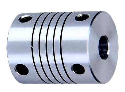
Flexible Motor Coupling:
A flexible motor coupling is designed to accommodate misalignment between the motor shaft and the driven equipment shaft. It uses flexible elements, such as elastomeric materials, to provide some degree of flexibility and damping. The key differences are:
- Misalignment Compensation: Flexible couplings can handle both angular and parallel misalignment between the motor and driven equipment shafts. This flexibility reduces stress on bearings and allows for a smoother transmission of torque.
- Shock Absorption: The elastomeric elements in flexible couplings can absorb and dampen vibrations and shock loads, protecting the motor and driven equipment from damage.
- Applications: Flexible couplings are commonly used in applications where misalignment is expected, such as pumps, compressors, conveyors, and machine tools.
Rigid Motor Coupling:
A rigid motor coupling provides a solid and inflexible connection between the motor shaft and the driven equipment shaft. It does not allow any misalignment and offers a direct torque transmission path. The key differences are:
- No Misalignment Compensation: Rigid couplings do not accommodate misalignment between the motor and driven equipment shafts. Proper alignment is critical for their efficient operation.
- Stiffness: Rigid couplings offer high torsional stiffness, maintaining precise alignment between the shafts and enabling accurate torque transmission.
- Applications: Rigid couplings are used in applications where precise alignment is required, such as high-precision machine tools, robotics, and applications with low or negligible misalignment.
The choice between a flexible motor coupling and a rigid motor coupling depends on the specific requirements of the application. Flexible couplings are preferred when misalignment is expected, while rigid couplings are suitable for applications where precise alignment and direct torque transmission are essential for the system’s performance.
“`

editor by CX 2024-05-06
by
Tags:
Leave a Reply