Product Description
Hot sale: low noise,no leakage, no additional cost for motor coupling magnetic coupling pump motor shaft coupling
Please send us following information.
1. Motor output power(KW)
2. Motor speed(RPM)
3.Torque of the mangetic coupling
4. Working pressure of the housing(isolation sleeve)
5.Working temperature of magnetic coupling
6. Technical drawing of the output part connector (usually motor)
7. Technical drawing of the input part connector (usually pump)
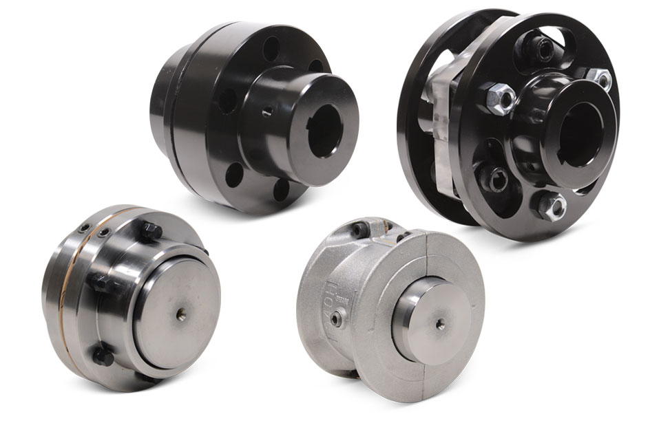
Introduction of motor coupling magnetic coupling pump motor shaft coupling
Magnetic shaft coupling is a new kind of coupling, which connects motor and machine by permanent magnetic force.
They are consisted of external rotor, internal rotor and isolating covers.
They work in the sealed magnetic drive pumps, which transporting volatile, flammable, explosive and toxic solutions with no leakage.
These magnetic shaft couplings can be used to connect gear pumps , screw pumps, centrifugal pumps, etc. with all types of electric motor or gear box.
Magnetic shaft coupling are widely used in various industries and fields, such as chemical, papermaking, foodstuff, pharmacy, and so on.
Advantages of motor coupling magnetic coupling pump motor shaft coupling
» Elimination of fluid leakage from the pump shaft.
» Vibrations are not transmitted to the pump.
» No maintenance required for magnetic couplings.
» Using magnetic couplings allows use of standard pumps without expensive mechanical seals.
» No additional cost for purchasing mechanical seal spare parts and maintenance.
Technical drawing of motor coupling magnetic coupling pump motor shaft coupling
Specification of motor coupling magnetic coupling pump motor shaft coupling
| Item | Internal Rotor(mm) | External Rotor(mm) | Isolating Covering(mm) | |||||||||||||||||
| A | B | C | D | E | F | G | Shaft Pin | H | I | J | L | N | M | P | Q | R | S | T | U | |
| GME03-3LM00 | Φ35 | – | Φ10 | 26 | – | 18 | – | M6X12 | Φ42 | Φ60 | Φ50 | 46 | 6-M4 | Φ40 | Φ50 | 4-Φ5.4 | Φ38 | Φ60 | 6 | 6 |
| GME03-5MM00 | Φ42 | – | Φ12 | 27 | 4 | 18 | 13.8 | M6X16 | Φ49 | Φ72 | Φ60 | 46 | 4-Φ6.7 | Φ52 | Φ60 | 4-Φ6.7 | Φ44 | Φ74 | 8 | 8 |
| GME03-16LM00 | Φ56 | – | Φ12 | 45 | 4 | 25 | 13.8 | M6X16 | Φ63 | Φ89 | Φ80 | 75 | 6-M5 | Φ70 | Φ75 | 4-Φ6.7 | Φ58 | Φ89 | 8 | 8 |
| GME03-16LM01 | Φ56 | – | Φ12 | 45 | 4 | 25 | 13.8 | M6X16 | Φ63 | Φ89 | Φ80 | 75 | 4-M5 | Φ70 | Φ75 | 4-Φ6.7 | Φ58 | Φ89 | 6 | 10 |
| GME03-16MM00 | Φ56 | – | Φ12 | 45 | 4 | 25 | 13.8 | M6X16 | Φ63 | Φ89 | Φ80 | 75 | 6-M5 | Φ70 | Φ75 | 4-Φ6.7 | Φ58 | Φ89 | 8 | 8 |
| GME03-22LM00 | Φ88 | – | Φ20 | 29 | 6 | 25 | 22.8 | M8X20 | Φ97 | Φ122 | Φ110 | 70 | 8-M6 | Φ98 | Φ108 | 6-Φ6.7 | Φ91 | Φ122 | 8 | 8 |
| GME03-30LM00 | Φ88 | – | Φ20 | 48 | 6 | 30 | 22.8 | M8X20 | Φ97 | Φ122 | Φ110 | 81 | 8-M6 | Φ98 | Φ108 | 6-Φ6.7 | Φ91 | Φ122 | 8 | 8 |
| GME03-40LM00 | Φ101 | – | Φ25 | 49 | 8 | 28 | 28.3 | M10X20 | Φ109 | Φ140 | Φ124 | 83 | 8-M8 | Φ110 | Φ126 | 8-Φ6.7 | Φ103 | Φ140 | 12 | 6 |
| GME03-50LM00 | Φ107 | – | Φ20 | 70 | 6 | 30 | 22.8 | M6X16 | Φ113.4 | Φ145 | Φ135 | 80 | 4-M6 | Φ126 | Φ133 | 12-Φ8.7 | Φ109 | Φ153 | 12 | 15 |
| GME03-65LM00 | Φ101 | – | Φ25 | 77 | 8 | 45 | 28.3 | M10X20 | Φ109 | Φ140 | Φ124 | 111 | 8-M8 | Φ110 | Φ126 | 8-Φ6.7 | Φ103 | Φ140 | 12 | 6 |
| GME03-80LM00 | Φ106 | – | Φ32 | 65 | 10 | 21 | 36.5 | M6X25 | Φ115 | Φ145 | Φ135 | 82 | 4-M6 | Φ127 | Φ135 | 6-Φ8.7 | Φ110 | Φ153 | 13 | 18 |
| GME03-80LM00 | Φ141 | Φ92 | Φ40 | 65 | 12 | 45 | 43.3 | M12X25 | Φ152 | Φ180 | Φ168 | 100 | 8-M8 | Φ154 | Φ164 | 8-Φ6.7 | Φ145 | Φ180 | 12 | 8 |
| GME03-100LM00 | Φ131 | Φ82 | Φ32 | 80 | 10 | 24.5 | 35.3 | M8X35 | Φ139 | Φ170 | Φ160 | 100 | 4-M6 | Φ152 | Φ158 | 8-Φ8.7 | Φ133 | Φ178 | 14 | 21 |
| GME03-110LH00 | Φ141 | Φ92 | Φ40 | 85 | 10 | 50 | 43.3 | M12X25 | Φ152 | Φ184 | Φ168 | 115 | 12-M8 | Φ156 | Φ164 | 12-Φ6.7 | Φ145 | Φ180 | 12 | 3 |
| GME03-110LM00 | Φ141 | Φ92 | Φ35 | 80 | 10 | 55 | 38.3 | M12X25 | Φ152 | Φ180 | Φ168 | 115 | 12-M8 | Φ154 | Φ164 | 12-Φ6.7 | Φ145 | Φ180 | 12 | 3 |
| GME03-140LM00 | Φ141 | Φ92 | Φ40 | 110 | 12 | 80 | 43.3 | M12X25 | Φ152 | Φ190 | Φ170 | 145 | 12-M10 | Φ154 | Φ164 | 12-Φ6.7 | Φ145 | Φ180 | 12 | 3 |
| GME03-180LM00 | Φ141 | Φ92 | Φ40 | 140 | 12 | 95 | 43.3 | M12X25 | Φ152 | Φ190 | Φ170 | 175 | 12-M10 | Φ154 | Φ164 | 12-Φ6.7 | Φ145 | Φ180 | 12 | 3 |
| GME03-220LM00 | Φ141 | Φ92 | Φ48 | 160 | 14 | 110 | 51.8 | M12X25 | Φ152 | Φ190 | Φ170 | 195 | 12-M10 | Φ154 | Φ164 | 12-Φ6.7 | Φ145 | Φ180 | 12 | 3 |
| GME03-300LM00 | Φ162 | – | Φ65 | 100 | 18 | 60 | 69.4 | Φ170 | Φ198 | Φ188 | 123 | 12-M6 | Φ180 | Φ192 | 12-Φ11 | Φ163.5 | Φ218 | 16 | 10 | |
| GME03-400LH00 | Φ195 | – | Φ70 | 127 | 20 | 107 | 79.9 | M12X25 | Φ203 | Φ234 | Φ222 | 152 | 6-M6 | Φ212 | Φ164 | 12-Φ11 | Φ198 | Φ278 | 16 | 22 |
Application of motor coupling magnetic coupling pump motor shaft coupling
The ability to hermetically separate 2 areas whilst continuing to transmit mechanical power from one to the other makes these couplings ideal for applications where prevention of cross contamination is essential. For instance: hydraulic sectors, dosing systems, compressors, sterilizers, industrial ovens, biotechnology, subsea equipment, pharmaceutical industry, chemical industry, food industry, generators and mixers.
Operation principles of motor coupling magnetic coupling pump motor shaft coupling
The magnetic coupling works by using the power generated by permanent magnets. No external power supply is needed. These are permanent magnets not electro magnets.
Packing Method of motor coupling magnetic coupling pump motor shaft coupling
Double strength corrugated Carton and Wood case Sea Packing.
/* January 22, 2571 19:08:37 */!function(){function s(e,r){var a,o={};try{e&&e.split(“,”).forEach(function(e,t){e&&(a=e.match(/(.*?):(.*)$/))&&1
Best Practices for Installing a Motor Coupling for Optimal Performance
Proper installation of a motor coupling is essential to ensure optimal performance and reliability of the power transmission system. Follow these best practices when installing a motor coupling:
1. Correctly Match Coupling Type:
Select a motor coupling type that is suitable for the specific application and operating conditions. Consider factors like torque requirements, misalignment tolerance, and environmental factors when choosing the coupling.
2. Ensure Proper Alignment:
Achieve precise alignment between the motor and driven equipment shafts before installing the coupling. Misalignment can lead to premature wear and reduced efficiency.
3. Check Shaft Endplay:
Verify that the shafts have the correct endplay to allow for thermal expansion and contraction. Inadequate endplay can lead to binding or increased stress on the coupling and connected components.
4. Clean Shaft Surfaces:
Ensure that the shaft surfaces are clean and free of any debris or contaminants before installing the coupling. Clean surfaces promote proper coupling engagement and reduce the risk of slippage.
5. Use Correct Coupling Fasteners:
Use the specified fasteners, such as bolts or set screws, provided by the coupling manufacturer. Tighten the fasteners to the recommended torque values to secure the coupling properly.
6. Verify Keyway Alignment:
If the coupling has a keyway, ensure that it aligns correctly with the key on the motor and driven equipment shafts. Proper keyway alignment prevents rotational slippage and ensures efficient torque transmission.
7. Lubrication:
If the coupling requires lubrication, apply the appropriate lubricant as recommended by the manufacturer. Proper lubrication reduces friction and wear on coupling components.
8. Perform Trial Run:
Before putting the system into full operation, perform a trial run to check for any abnormalities or vibrations. Monitor coupling performance and check for leaks, noises, or other signs of issues.
9. Regular Inspection and Maintenance:
Conduct regular inspections and maintenance on the motor coupling and the entire power transmission system. Check for wear, alignment, and any signs of damage, and address any issues promptly.
10. Follow Manufacturer Guidelines:
Always follow the manufacturer’s installation guidelines and recommendations for the specific coupling model. Manufacturer guidelines provide essential information for optimal performance and safe operation.
By adhering to these best practices, you can ensure that the motor coupling functions efficiently and contributes to the overall performance and reliability of the mechanical system.
“`
Explaining the Concept of Backlash and Its Impact on Motor Coupling Performance
Backlash is a critical factor in motor coupling performance and refers to the clearance or play between mating components within the coupling. In the context of motor couplings, it specifically relates to the amount of free movement or angular displacement that occurs when there is a change in direction of the driven shaft without a corresponding immediate change in the driving shaft.
Backlash in motor couplings can occur due to several factors:
- Manufacturing Tolerances: Variations in the manufacturing process can lead to slight clearances between coupling components, introducing backlash.
- Wear and Tear: Over time, the coupling components may experience wear, leading to increased clearance and backlash.
- Misalignment: Improper alignment between the motor and driven equipment shafts can cause additional play in the coupling, resulting in increased backlash.
The impact of backlash on motor coupling performance includes the following:
1. Reduced Accuracy:
Backlash can lead to inaccuracies in motion transmission. When the direction of rotation changes, the free play in the coupling must be taken up before torque can be effectively transmitted. This delay in motion transfer can cause positioning errors and reduced accuracy in applications requiring precise movements.
2. Vibration and Noise:
Excessive backlash can cause vibration and noise during operation. The sudden engagement of the coupling components after a change in direction can create shocks and vibrations that may affect the overall system performance and lead to premature wear of coupling components.
3. Reduced Efficiency:
Backlash results in power loss, especially in applications with frequent changes in direction. The energy required to take up the clearance in the coupling reduces the overall efficiency of power transmission.
4. Wear and Fatigue:
Repeated impacts due to backlash can accelerate wear and fatigue of coupling components, leading to a shorter lifespan and potential coupling failure.
5. Safety Concerns:
In certain applications, particularly those involving heavy machinery or high-speed operations, excessive backlash can pose safety risks. The lack of immediate response to directional changes can affect the control and stability of the equipment.
To mitigate the effects of backlash, it is essential to select motor couplings with low or controlled backlash and to maintain proper alignment during installation. Regular inspection and maintenance can help identify and address any increasing backlash, ensuring the motor coupling operates with optimum performance and reliability.
“`
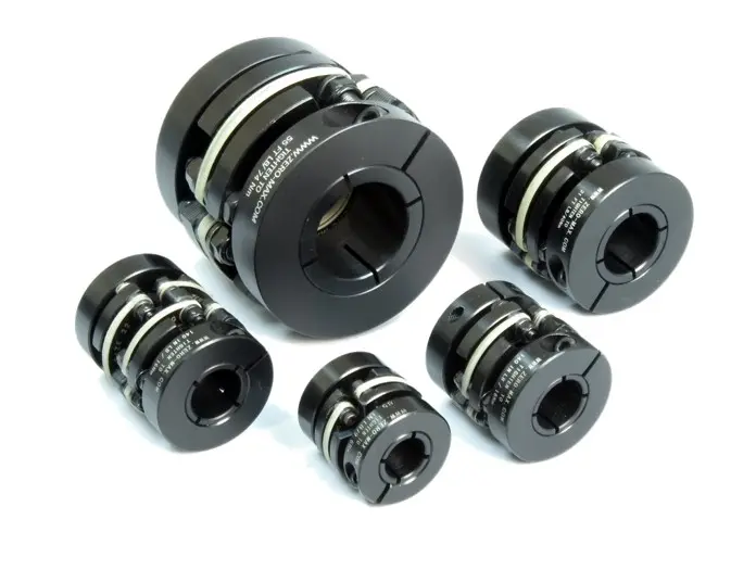
How Does a Flexible Motor Coupling Differ from a Rigid Motor Coupling?
Flexible motor couplings and rigid motor couplings are two distinct types of couplings used to connect motors to driven equipment. They differ significantly in their design, function, and applications:
Flexible Motor Coupling:
A flexible motor coupling is designed to accommodate misalignment between the motor shaft and the driven equipment shaft. It uses flexible elements, such as elastomeric materials, to provide some degree of flexibility and damping. The key differences are:
- Misalignment Compensation: Flexible couplings can handle both angular and parallel misalignment between the motor and driven equipment shafts. This flexibility reduces stress on bearings and allows for a smoother transmission of torque.
- Shock Absorption: The elastomeric elements in flexible couplings can absorb and dampen vibrations and shock loads, protecting the motor and driven equipment from damage.
- Applications: Flexible couplings are commonly used in applications where misalignment is expected, such as pumps, compressors, conveyors, and machine tools.
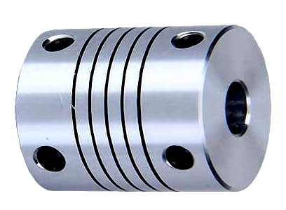
Rigid Motor Coupling:
A rigid motor coupling provides a solid and inflexible connection between the motor shaft and the driven equipment shaft. It does not allow any misalignment and offers a direct torque transmission path. The key differences are:
- No Misalignment Compensation: Rigid couplings do not accommodate misalignment between the motor and driven equipment shafts. Proper alignment is critical for their efficient operation.
- Stiffness: Rigid couplings offer high torsional stiffness, maintaining precise alignment between the shafts and enabling accurate torque transmission.
- Applications: Rigid couplings are used in applications where precise alignment is required, such as high-precision machine tools, robotics, and applications with low or negligible misalignment.
The choice between a flexible motor coupling and a rigid motor coupling depends on the specific requirements of the application. Flexible couplings are preferred when misalignment is expected, while rigid couplings are suitable for applications where precise alignment and direct torque transmission are essential for the system’s performance.
“`

editor by CX 2024-05-09
by
Leave a Reply